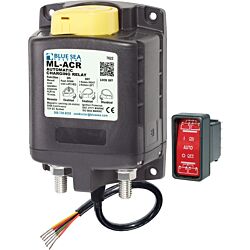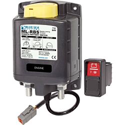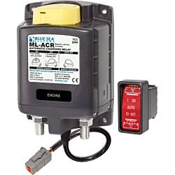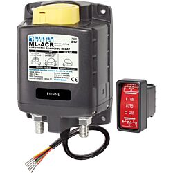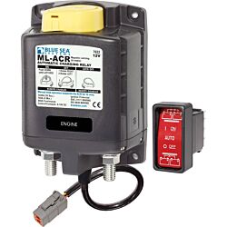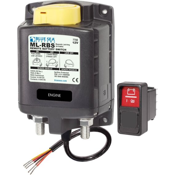
500 Amp magnetic latching switch provides high amperage switching under load, manually or from remote locations
- Manual override knob provides an added level of safety allowing control with or without power and offering LOCKED OFF capability for servicing
- LED output to remotely indicate switch state - requires optional LED
- 3∕ 8"-16 tin-plated copper studs for maximum conductivity and corrosion resistance
- 7∕ 8" (22 mm) stud length accepts multiple cable terminals
- Label recesses for circuit identification
- Silver alloy contacts provide high reliability for switching live loads
| Specifications | |
|---|---|
| Control Circuit Connection | Tinned Wire* |
| Nominal Voltage | 12V DC |
| Manual Control** | Yes |
| Coil Function*** | Bi-Stable |
| Mounting | #10 |
| Amperage Operating Current | 0mA**** |
| Amperage Operating Current when changing state | <7A (40 ms) |
| Terminal Stud Torque | 140 in-lb (15.82 Nm) |
| Control Circuit Voltage | 9-16V DC |
| Continuous Rating***** | 500A |
| Intermittent Rating****** | 700A (5 min) |
| Cranking Rating 30 sec******* | 1450A DC |
| Minimum Operating Temperature | -10° C |
| Maximum Operating Temperature | 60° C |
| Cable Size to Meet Ratings | 2x (4/0) |
| Live Current Switching | 300A @ 12V DC******** |
| Master Control Switch Capability | No |
| Mechanical Endurance | 100,000 Cycles |
| Terminal Ring Diameter Clearance | 1.18in (29.97 mm) |
| Terminal Stud Length | 0.875in (22.23 mm) |
| Terminal Stud Size | 3/8" - 16 (M10) |
| Weight | 2.05lb (0.93 kg) |
*Provided on retail units
**Manual control switch provides an added level of safety allowing control with or without power, and offering LOCK OFF capability for servicing.
***Auto releasing provides 500A switching and features of current ML Remote Battery Switches, but can be controlled with SPST or SPDT switch for applications where a normally open relay is desired.
****@ 25°C nominal VDC
*****The maximum current a switch is designed to conduct for an indefinite period.
******The maximum amount of current a switch is designed to carry for a minimum of a designated period of time.
*******Normally associated with 'cranking current' which is the current required by the starter circuit prior to engine starting. The cranking current varies significantly during the starting cycle. Initially, there is a large surge of current required to overcome the inertia and compression of the engine. This surge can be two to four times the average cranking current. Once the engine is turning there are peaks and valleys as the pistons go through the compression and exhaust cycles. The cranking current rating is used for sizing batteries, cables, and battery switches.
********10,000 Cycles


